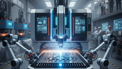
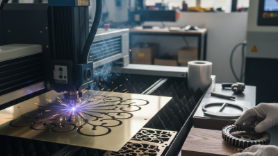
Laser cut parts are components shaped by a focused laser beam, guided by digital design data. They appear in machinery, electronics, architectural models, automotive assemblies, and custom product development. The process can cut steel, aluminum, stainless steel, acrylic, wood, and selected engineering plastics. Each material reacts differently to heat, speed, and beam power.
A typical workflow begins with a CAD drawing. The operator checks dimensions, material thickness, edge requirements, and internal features. Software then converts the design into cutting instructions. On the machine, a high-energy beam follows programmed paths while assist gas clears molten material from the kerf. The result may include clean holes, narrow slots, and detailed profiles. It looks simple.
It is not always simple.
Experienced manufacturers inspect the first article before producing a larger batch. They measure critical edges, review heat-affected areas, and check whether small features remain stable. Tolerances depend on the machine, material, thickness, and design geometry. A thin stainless steel bracket may need different settings from a thick carbon steel plate. Surface oxidation, slight taper, or burrs can still appear. These details deserve honest attention.
This guide explains what laser cut parts are and how professionals make them reliably. It also examines design choices, material selection, cutting stages, quality control, and practical limitations. The best results come from cooperation between accurate drawings and informed machine setup. A digital file alone cannot guarantee a perfect component. Careful decisions matter.
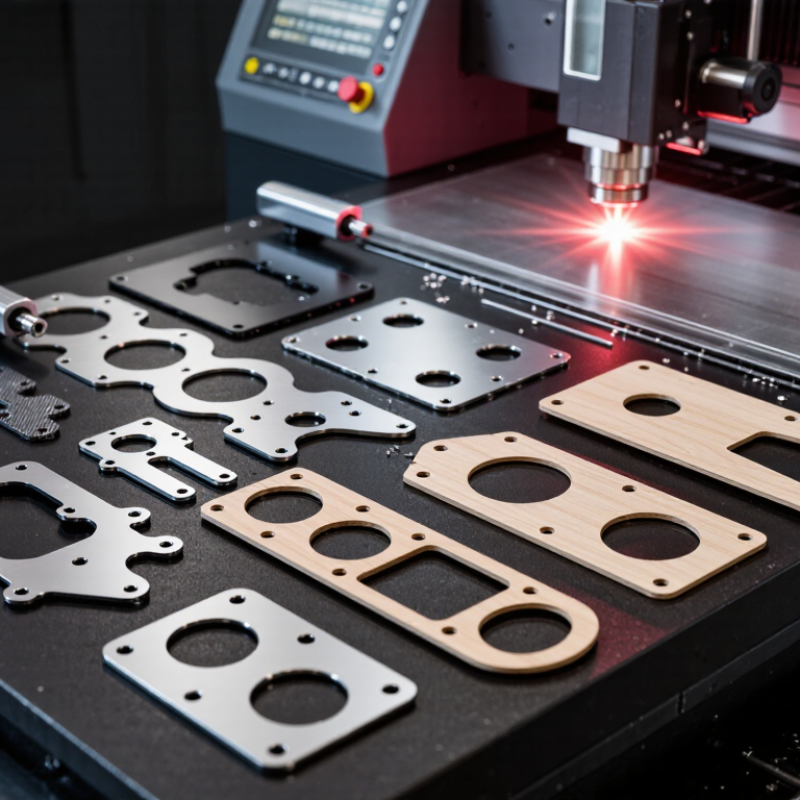
Laser-cut parts are components shaped from sheet material by a focused laser beam. The beam follows a digital drawing and removes material along programmed lines. This process can produce brackets, panels, gears, covers, and detailed prototypes. Common materials include steel, aluminum, stainless steel, acrylic, plywood, and selected engineering plastics.
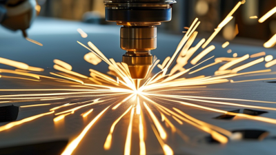
The cutting head concentrates intense heat into a narrow point. Assist gas pushes away molten material and helps protect the cut edge. Before production, an operator checks material thickness, drawing scale, kerf width, and hole size.
A small error in any of these details can affect assembly. It happens more often than people expect.
After cutting, parts may show slight discoloration, burrs, or heat marks, depending on the material and settings. Edges can be deburred, brushed, or left as cut when appearance is not critical.
Reliable laser-cut parts depend on more than machine power. Operators inspect dimensions with calipers, gauges, or coordinate equipment. They also compare the first piece with the approved drawing. Tight tolerances require careful testing, not optimistic promises. In practical work, a design may look perfect on screen but fail because a bend allowance or screw clearance was overlooked. Reviewing those weak points early usually saves material, time, and rework.
Laser cut parts are shaped by a focused beam that removes material along a programmed path. The process can create clean edges, narrow slots, and repeated components with impressive consistency. Material choice, however, often matters more than cutting speed. Each sheet reacts differently to heat, pressure, and beam energy.
Metals such as mild steel, stainless steel, aluminum, and brass can be processed with suitable laser systems. Thin metal sheets usually produce precise brackets, panels, and machine covers. Wood, plywood, acrylic, cardboard, leather, and many fabrics are also common choices. Acrylic can form smooth, polished edges, while wood may show darkened marks near the cut. That contrast can look attractive, but it may be unwanted on visible parts. Glass and ceramics require specialized equipment and careful settings. They are more likely to crack from uneven thermal stress.
Some materials should not enter a laser cutter. Plastics containing chlorine can release highly corrosive and dangerous fumes. Unknown plastic sheets are risky, even when they appear harmless. Reflective metals can redirect energy and damage equipment unless the machine is designed for them. In practical work, I check the material composition, thickness, and safety data before cutting. I also test a small sample because published settings are only starting points. The result is not always perfect. Warping, rough corners, or heat discoloration can still appear, especially when ventilation or focus is slightly wrong.
| Material Category | Common Materials | Typical Laser Compatibility | Typical Processable Thickness* | Typical Applications | Important Processing Notes |
|---|---|---|---|---|---|
| Mild Steel | Low-carbon steel sheet and plate | Fiber laser; CO₂ laser can also be used | Approximately 0.5–25 mm, depending on laser power and machine capacity | Brackets, frames, panels, machine parts | Fast cutting and clean edges are possible; thicker sections may require slower speeds and assist gas. |
| Stainless Steel | Austenitic and ferritic stainless-steel sheet | Fiber laser; CO₂ laser is also suitable for many grades | Approximately 0.5–20 mm | Food equipment, enclosures, medical and architectural parts | Nitrogen assist gas is commonly used when a bright, low-oxidation edge is required. |
| Aluminum | Aluminum sheet, plate and selected alloys | Fiber laser | Approximately 0.5–15 mm | Lightweight housings, transport parts, heat-management components | High reflectivity and thermal conductivity require suitable power, focus and cutting parameters. |
| Copper and Brass | Copper sheet, brass sheet and thin plate | High-power fiber laser with reflective-material capability | Approximately 0.5–6 mm, depending on alloy and equipment | Electrical parts, heat exchangers, decorative components | These materials reflect infrared laser energy strongly and require appropriate safety controls and process settings. |
| Wood and Plywood | Hardwood, softwood, plywood and MDF | CO₂ laser | Approximately 1–20 mm; thicker material may need multiple passes | Signs, prototypes, furniture details, packaging inserts | The cut edge is typically darkened or charred; resin content and moisture affect the result. |
| Acrylic and Selected Plastics | Acrylic, polycarbonate-free plastic sheets, PET and some engineering plastics | CO₂ laser for many non-reflective plastics | Approximately 1–15 mm, material dependent | Displays, light guides, templates, protective covers | Only known laser-safe plastics should be processed; chlorine-containing materials can release hazardous gases. |
| Paper, Cardboard and Textiles | Paperboard, corrugated cardboard, cotton, felt and some synthetic fabrics | CO₂ laser | Approximately 0.1–10 mm, depending on structure and density | Packaging, gaskets, fashion patterns, craft components | Low power and high travel speed help reduce scorching and unwanted thermal deformation. |
| Glass and Ceramics | Glass, ceramic tile and selected brittle non-metallic materials | Specialized laser processes; conventional cutting is limited | Usually thin sections or surface-marking applications | Engraving, marking, scoring and precision microprocessing | Thermal shock can cause cracking; equipment and parameters must be selected for the specific material. |
Laser cut parts are components shaped from sheet metal, plastics, wood, or other suitable materials. A focused laser beam removes material along a programmed path. This method produces clean edges, narrow cuts, and detailed profiles. Precision starts with preparation.
The process begins with a digital drawing, often created in CAD software. The drawing is converted into machine instructions that control movement, power, speed, and cutting order. Technicians check the material thickness and adjust the laser focus accordingly. Heat does the cutting.
During operation, the beam concentrates intense energy on a small point. The material melts, burns, or vaporizes, depending on its composition. Compressed assist gas clears debris from the cut and helps protect the edge. A slight line width, called the kerf, must be included in accurate designs.
After cutting, operators inspect dimensions, corners, holes, and surface condition. They may remove small residues or sharp edges by hand. In practical workshops, the first piece often needs a minor adjustment. Material batches can react differently, even when specifications appear identical. That is where experience matters. A fast setting may increase heat marks, while a slow setting can widen the cut. The process is precise, but never magical. Careful testing remains necessary, especially for thin sheets, reflective materials, or complex shapes. Inspections with calipers and visual checks help confirm that each part matches the approved drawing.
Laser-cut parts are produced by directing a focused beam through a CNC-controlled cutting head. Fiber lasers commonly process steel, stainless steel, and aluminum sheets. CO2 systems remain useful for some non-metal materials. A 2024 Grand View Research analysis valued the global laser cutting machine market at more than US$6 billion, reflecting wider industrial adoption. The International Federation of Robotics also reported that Asia installed about 70% of new industrial robots in 2023. Automation is becoming normal, not optional.
Settings determine the edge quality. Operators adjust laser power, cutting speed, focal position, assist-gas pressure, nozzle distance, and piercing time. A 3 mm stainless-steel sheet may need a smaller nozzle gap and nitrogen assistance to reduce oxidation. Excessive power can widen the kerf and create a heat-affected edge. Too much speed may leave dross underneath. Small changes matter.
Test pieces reveal more than software estimates. A practical operator checks the first cut with a magnifier, caliper, and roughness comparison. ISO 9013 provides quality classifications for thermal-cut edges, but real production still depends on material batches and machine condition. That is the imperfect part. A clean chart cannot replace a failed test coupon. Even experienced technicians sometimes chase speed and lose consistency.
Laser-cut parts require careful inspection after cutting. Heat can create discoloration, slight warping, or hardened edges. Inspectors check dimensions with calipers, micrometers, and coordinate measuring equipment. They compare critical features with the approved drawing.
Hole diameter
Slot position
Overall flatness
Hole diameter, slot position, and overall flatness deserve close attention.
Visual checks reveal burrs, scratches, dross, and incomplete cuts. Surface roughness may also affect assembly or sealing performance. Inspection records should identify the material, batch, operator, and measurement results. This traceability supports consistent production.
However, no inspection method is perfect. A rushed check can miss a small distortion near a corner.
Tips: Use clean gauges. Inspect cooled parts. Measure critical areas twice. Keep protective film on finished surfaces when possible.
Finishing depends on the part’s purpose and material. Operators may deburr edges by hand, brushing, tumbling, or controlled machining. They can then clean, polish, coat, or mark the surface. Each process should preserve essential dimensions.
For example, excessive grinding may soften a sharp feature or enlarge a hole.
Experienced technicians inspect the part again after finishing, not only before it. This second check often catches damage caused during handling. Practical judgment matters, but documented procedures make that judgment more reliable.
Please fill out this form and we will get an order or estimate ready for you. Please give us as much detail as you can for us to get started, and we will contact you to finsh the work order.