How to Use a 90° Peel Strength Tester?
Using a 90° Peel Strength Tester can look straightforward: secure the sample, set the angle, start the test, and record the force. The real challenge is controlling every small detail that influences the result. Strip width, backing stiffness, adhesive thickness, peel speed, and clamping alignment can change the force curve. A careless setup may produce attractive data, but not dependable evidence.
Dr. A. J. Kinloch, a leading researcher in adhesive bonding, stated, “The performance of an adhesive joint depends on the properties of the adhesive, the adherends, and the interface.” This principle remains highly relevant when evaluating labels, tapes, films, laminates, and flexible packaging. Before testing, inspect the specimen for wrinkles, contamination, uneven bonding, or damaged edges. Condition it under the required temperature and humidity. Then verify the tester’s calibration and confirm that the peel arm moves smoothly at exactly 90 degrees.
The procedure is simple. The judgment is not. Watch the live force curve, not only the final average. Note sudden peaks, adhesive transfer, substrate tearing, and irregular peeling. These details can explain why two specimens from one batch behave differently. It is also worth admitting that perfect repeatability is uncommon. Operators may overlook small alignment errors or assume that a stable machine guarantees stable results. It does not. A reliable test combines correct equipment settings, careful specimen preparation, consistent observation, and honest reporting. This guide explains how to operate a 90° Peel Strength Tester safely, reduce avoidable variation, and interpret results with practical caution.
Understanding the Purpose and Working Principle of a 90° Peel Strength Tester
How to Use a 90° Peel Strength Tester?
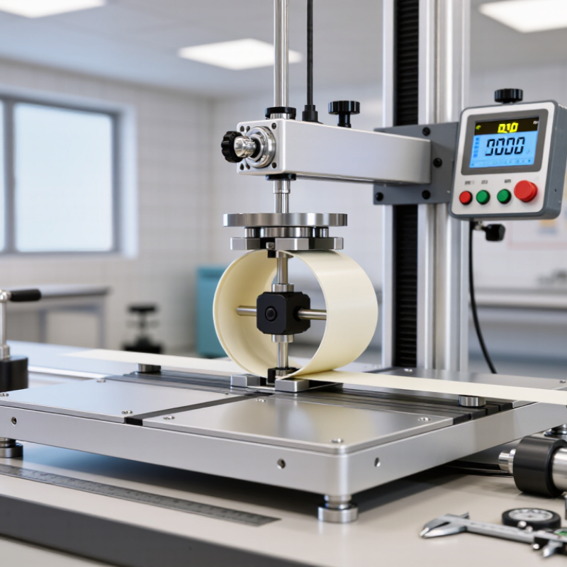
A 90° peel strength tester measures the force needed to separate an adhesive layer from a surface at a right angle. This test helps engineers evaluate bonding performance, coating consistency, and material compatibility. It is useful for tapes, labels, films, laminates, and protective coverings. The tester uses a motorized clamp and a calibrated load cell. As the machine pulls the sample, it records force over distance. Results are commonly reported in N/25 mm or N/10 mm.
The purpose is not simply to obtain one large number. A reliable test reveals how steadily the adhesive resists peeling. Prepare a clean substrate and cut equal-width specimens. Apply consistent pressure, then allow the bond to condition under controlled temperature and humidity. Fix the free end in the clamp and maintain a true 90° angle. Use the specified peeling speed. Record the average force, peak force, and unusual failure marks. I often inspect the peeled surface afterward. Adhesive residue can expose problems that the graph misses. Real samples are rarely ideal. Slight alignment errors can influence the result.
Tips: Calibrate the load cell before testing. Check the peel angle during the run. Remove damaged specimens. Test several samples, not one. Keep a clear record of surface preparation and conditioning time. If results vary widely, review the substrate, pressure, and cutting method before changing the adhesive. That step is easy to overlook.
Preparing Test Specimens and Configuring the Testing Equipment
Before using a 90° peel strength tester, prepare specimens with consistent dimensions and clean handling. Cut adhesive strips to 25 mm wide and at least 175 mm long. Avoid touching the bonding surface. Dust, skin oil, and uneven edges can distort results. Condition the adhesive, backing, and substrate at 23°C and 50% relative humidity when possible. These conditions align with commonly used pressure-sensitive adhesive testing practices.
Apply each specimen with a controlled roller and record the pressure, number of passes, and dwell time. A 20-minute dwell may support routine comparisons, while longer dwell periods can reveal bonding changes over time. Mount the free end so the peel angle remains close to 90°. Set a constant crosshead speed, often 300 mm/min under established 90° peel procedures. The 2024 Grand View Research market outlook describes pressure-sensitive adhesives as a roughly 6% annual-growth sector, increasing the need for repeatable laboratory data. Small setup differences matter.
Check calibration before testing. Confirm the load cell range, grip alignment, and zero reading. The specimen should peel smoothly, not jerk across the fixture. Record average force, peak force, failure mode, temperature, humidity, and substrate type. I have seen operators discard irregular traces too quickly. That can hide useful evidence. A crooked specimen may indicate poor preparation, not random equipment error. Repeat at least five specimens when material variation is suspected, then review the scatter rather than reporting only the highest value.
Performing the 90° Peel Strength Test Step by Step
How to Use a 90° Peel Strength Tester?
Performing the 90° Peel Strength Test Step by Step
Begin by conditioning the bonded samples under the required temperature and humidity. Cut each specimen to a consistent width, commonly 25 mm. Clean the fixture and remove loose adhesive. Mount the flexible layer without wrinkles. Keep the peeled tail aligned with the tester’s path. ASTM D6862 defines a 90° peel geometry for adhesive evaluation, while ISO 8510-1 covers similar flexible-to-rigid assemblies. Check the selected standard before setting speed or specimen dimensions.
Set the peel angle to 90° ± 1°. Secure the rigid panel firmly. Apply the required preload, then start the crosshead smoothly. Watch the force curve, not only the final number. Record the average peel force, peak force, and failure mode. Many laboratories report results in N/25 mm when using a 25 mm specimen width. Test at least five specimens when the procedure allows it. A clean curve is not guaranteed. Edge lifting, uneven coating, or trapped air can distort the result.
After testing, compare the traces for unusual variation. If one value differs sharply, inspect that specimen before deleting it. The failure may reveal a real process problem. ASTM D3330 Method F also emphasizes controlled 90° peel measurement for pressure-sensitive materials. Keep the raw curves, conditioning details, equipment calibration date, and operator notes. If the first run looks perfect, question it. Repeatability matters more than one impressive value.
Interpreting Results and Maintaining Test Accuracy
How to Use a 90° Peel Strength Tester? Interpreting Results and Maintaining Test Accuracy
A 90° peel test measures the force required to separate a bonded material at a right angle. Secure the flexible strip without twisting it. Align the peel line with the tester’s loading axis. Small alignment errors can change the force curve. They matter more than many operators expect. ASTM D6862-23 and ISO 8510-2 recommend recording specimen width, conditioning, peel rate, adhesive type, and failure mode. Report results in N/25 mm or another clearly stated unit.
Interpret the average together with the force curve. A stable plateau usually indicates consistent separation. Sharp peaks may show edge lifting, surface contamination, or uneven adhesive contact.
Cohesive failure leaves adhesive on both surfaces, while adhesive failure leaves one surface clean. These details explain the number. They do not replace it.
For example, three readings of 18.4, 19.1, and 17.8 N/25 mm average 18.4 N/25 mm, but the spread deserves review. Do not hide it.
Accuracy depends on preparation.
Condition specimens at a controlled temperature and humidity before testing. Clean the fixture, verify the load cell, and inspect the roller surface. Run a reference material at scheduled intervals. Keep the backing flat and trim damaged edges. ASTM and ISO methods stress repeatable conditioning and documented procedures, yet laboratories sometimes treat them as paperwork. That is a mistake. A perfect-looking result can still be poorly controlled. Record anomalies, even when they seem inconvenient.

