
Choosing the right Vertical Boring Machine starts with the workpiece, not the sales brochure. Measure its maximum diameter, height, and weight. Then consider the material, required tolerances, and production volume. A wide casting may fit the table but still exceed the machine’s load capacity. Small details matter.
Manufacturing engineer Taiichi Ohno wrote, “We are reducing that time line by removing the non-value-added wastes.” That principle offers a useful lens for machine selection: look beyond purchase price and ask where production time is lost. Will setup take hours? Can the operator reach the cutting area easily? Is the spindle’s torque suited to heavy cuts, or is speed more important for finishing? A machine that looks capable on paper may disappoint on the shop floor.
This guide examines table capacity, ram travel, spindle performance, control systems, tooling, installation, and after-sales support. It also considers the less visible costs: foundation work, energy use, maintenance access, and operator training. Bring a real part drawing and a typical job plan when comparing models. A supplier’s demonstration is more useful when it reflects your actual work. Still, no checklist replaces careful verification. Machine specifications can be easy to misread, and I would not assume every quoted capacity suits every setup.
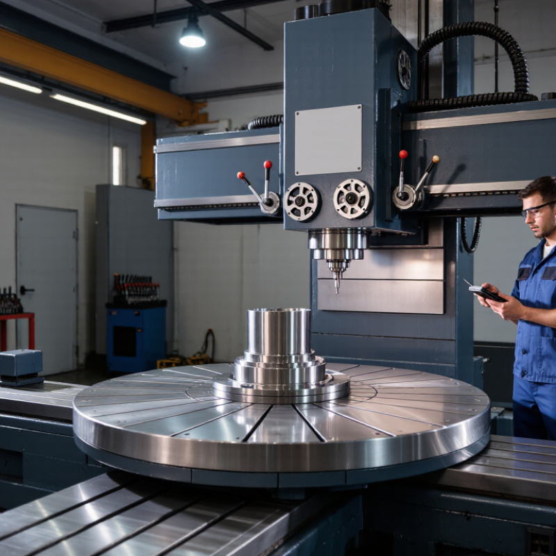
Choosing the right vertical boring machine starts with understanding its operating axes. A vertical boring mill holds a large workpiece on a horizontal rotating table, with the workpiece axis standing upright. The cutting tool moves vertically along the Z axis and often radially along X. The table’s rotation is commonly identified as the C axis.
A vertical turning lathe uses a similar arrangement: the workpiece rotates on a horizontal table, while cutting tools approach from above or beside it. Both machine types can handle heavy, wide parts that are difficult to mount horizontally. In practice, “vertical boring mill” and “vertical turning lathe” may describe overlapping equipment. The name alone does not tell you every capability. Small details matter. Check the machine’s tool head, crossrail, travel, and boring capacity against the part’s dimensions and machining needs. I would not assume that two machines with similar names have the same axis travel.
Tips: Confirm the actual axis movements in the machine specifications. Ask how much clearance is available above the table, and verify the maximum workpiece diameter and weight. A part may fit on paper but still be awkward to load or machine. Look closely at the setup.

A vertical boring machine’s table must clear the complete setup, not just the workpiece. Measure the largest outside diameter in millimetres, including clamps, a faceplate, and any projecting features. Then compare it with the machine’s usable table diameter and maximum swing. Leave room for tool travel and safe clamping; a part that barely fits on paper may be awkward to machine. Measure the full setup.
Check the load rating in tonnes against the combined mass of the workpiece, fixture, and clamps. Do not assume the rated capacity applies equally to every loading arrangement. A heavy casting placed off-centre can create more stress than a lighter, evenly supported part. Confirm allowable load distribution and any centre-of-gravity limits in the machine’s technical documentation. For example, a 6-tonne workpiece with a 1-tonne fixture needs capacity for at least 7 tonnes, plus an appropriate operating margin. This estimate can still miss details, especially when the casting’s mass is uncertain. Weigh it where possible, and ask the supplier to verify unusual or offset setups before selection.
Choosing spindle power, torque, and RPM starts with the material and the cut—not the machine’s maximum rating. Gather the workpiece material, bore diameter, cutting speed, feed, depth of cut, and tool data. Use the tool supplier’s recommended cutting range as a starting point, then calculate spindle speed from cutting speed and bore diameter. A large bore needs fewer RPM than a small one at the same surface speed. Start with the cut.
Torque matters when the tool engages heavily, especially at low speeds or during rough boring. Check the machine’s torque curve, not just its headline power figure. A motor may deliver enough power at high RPM but lose useful torque in a lower speed range. For steel or cast iron, a conservative feed and steady torque can help prevent chatter and edge damage. Aluminum often permits higher cutting speeds, but long chips and tool geometry still affect the result. That matters.
Match the chosen speed range and continuous spindle power to the actual material removal rate. Leave capacity for interrupted cuts, imperfect setups, and heavier-than-planned stock. I would verify the figures with a trial cut and inspect chip shape, sound, surface finish, and tool wear. Cutting data is a guide, not a promise; workpiece rigidity and boring-bar overhang can change the result. A slightly cautious setup may be slower, but it is easier to trust.
When comparing vertical boring machines, ask for axis positioning results measured under ISO 230-2, not just a general accuracy claim. The standard assesses how closely an axis reaches commanded positions and how consistently it repeats them. Small errors matter. Request unidirectional and bidirectional results, since approaching a point from opposite directions can reveal reversal effects. Check the tested travel range, measurement interval, ambient temperature, and instrument uncertainty. A laser interferometer may be used, but the test setup and calibration matter as much as the number on the report.
Relate the results to the jobs you actually run. A long Z-axis travel, for example, may show different deviations at the lower and upper ends. Ask whether measurements cover the positions used for your typical workpieces, and whether the machine was thermally stabilized. Repeatability is useful, but it does not cancel systematic positioning error. Nor does an ISO 230-2 report guarantee finished-part accuracy; cutting forces, tooling, setup, and temperature changes still affect results. A tidy chart can be reassuring, yet it may miss your operating conditions. I would compare the stated tolerances with your part requirements, then confirm critical features through a practical machining trial. Some uncertainty remains. That is worth discussing before purchase.
Choosing a vertical boring machine starts with the workpiece, not the control screen. Measure maximum swing, bore depth, workpiece mass, and typical setup needs. Check that boring bars, facing heads, inserts, and tool-change clearances suit real jobs. A long bar can chatter in a deep bore, even when spindle power looks generous. Ask for a trial cut in representative material and inspect the finish, chip flow, and repeatability. Numbers help. Real cuts reveal tradeoffs.
CNC features should reduce setup errors, not merely add menus. Look for clear offset controls, program simulation, tool-life tracking, and recovery after interrupted cycles. Verify axis travel and spindle speed against your tolerances and batch size. If practical, request a demonstration using your part geometry. Operators should be able to understand alarms without guessing. I would not treat a feature list as proof of productivity; shop conditions often expose inconvenient gaps.
Tips: Apply ISO 12100 risk-assessment principles to setup, machining, cleaning, and maintenance. Check guarding, interlocks, emergency stops, safe access, and exposure to chips or coolant. Confirm documented risk-reduction measures and operator training with a qualified safety professional. ISO 12100 guides risk assessment; it does not by itself certify a machine. Keep the checklist near the machine, and review it after process changes.
Assess tooling, CNC features, and machine safety under ISO 12100.
How to use this chart: ISO 12100 presents risk reduction as a three-step sequence, not as a performance score. First consider inherently safe design, then safeguarding and complementary protective measures, and finally information for use.
For machine selection: Check that tooling and workholding suit the part and cutting operation; confirm CNC functions support the required setup and control; and review guarding, interlocks, access, and operating instructions as part of the machine’s risk assessment.
Please fill out this form and we will get an order or estimate ready for you. Please give us as much detail as you can for us to get started, and we will contact you to finsh the work order.